Crosstalk is a phenomenon by which a logic transmitted in vlsi circuit or a netwire creates undesired effect on the neighboring circuit or netswires due to capacitive coupling. If we have crosstalk then we might lose data or gain some extra datalogic which was not required.

Placement Vlsi Physical Design For Freshers
From the below picture we can see that.

. Value of acceptable IR drop will be decided at the start of the project and it is one of the factors used to determine the derate value. Note that far end crosstalk can be positive. Crosstalk is a phenomenon by which a logic transmitted in vlsi circuit or a netwire creates undesired effect on the neighbouring circuit or netswires due to capacitive coupling.
Crosstalk is the undesirable electrical interaction between two or more adjacent nets due to capacitive cross-coupling. In the next section we would discuss the crosstalk mechanism in VLSI Design. He is a Physical Design Engineer in eInfochips working in the backend design domain.
Crosstalk occurs via two mechanisms. These are basically called as VIAs. Start Today With A Special Discount.
When you perform crosstalk analysis using PrimeTime SI a change in delay due to crosstalk along the common segment of a clock path can be pessimistic but only for a zero-cycle check. Crosstalk in VLSI interconnections. Presented at the 1999 International Conference on VLSI Design.
This video will give you a quick overview of various fixing methods that can be applied during eco implementation phase in ASIC physical design in VLSIFollo. What Is the Importance of IR Drop Analysis. Crosstalk is becoming a major issue in deep submicron VLSI design due to high frequency high density and long interconnecting lines and small spacing between interconnections today.
12 DECEMBER 1999 1817 Short Papers Crosstalk in VLSI Interconnections Ashok Vittal Lauren Hui Chen Malgorzata Marek-Sadowska Kai-Ping Wang and Sherry Yang Abstract We address the problem of crosstalk computation and. CRPR and Crosstalk Analysis. Therefore the second class of crosstalk noise modeling methods aims to further improve the efficiency of noise analysis such that they can be used in the inner loop of physical design automation tools.
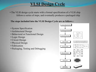
To connect between different metal layers we need poly layer along with the metal layers that we are going to connect. 4 Physical Design Cycle The input of the physical design cycle is a circuit diagram and the output is the layout of the circuit. IR drop determines the level of voltage at the pins of standard cells.
Koehl Analysis reduction and avoidance of crosstalk on VLSI chips in Proceedings of the International Symposium on Physical Design 1998 doi. Integrated circuits-oVery large scale integration--Design and construction--Data processing. For PCBs far end crosstalk is usually negative current due to Lm larger than current due to Cm.
Ad Learn VLSI Online At Your Own Pace. Minimisation of crosstalk in VLSI 1 Presented By. Sini Mukundan January 25 2017.
IEEE TRANSACTIONS ON COMPUTER-AIDED DESIGN OF INTEGRATED CIRCUITS AND SYSTEMS VOL. Crosstalk is the unwanted coupling of energy between two or more adjacent lines which can change the required signal and is also termed as Xtalk Occurs on long adjacent wires Can be interpreted as the coupling of energy from 1 line to another via. However in deep submicron VLSI chip designs there is often the need to assess and avoid crosstalk noise in the early stages of the chip design flow.
Algorithms for VLSI physical design automation Naveed A Sherwani. ISBN 978-1-4757-2221-5 ISBN 978-1-4757-2219-2 eBook DOI 101007978-1-4757-2219-2 1. Crosstalk induced noise Voltage profile of coupled noise Near end crosstalk is always positive currents from Lm and Cm always add and flow into the node.
Switching of the signal in one net aggressor can interfere neighbouring net victimdue to cross coupling capacitance this is called cross talk. In VLSI we have same situation with the nets routed that even nets are at their track but impacted by the noise from other nets. VIAs in VLSI.
These values are defined so that optimization and analysis can ensure that the spurious signals. Signal integrity and crosstalk are quality checks of the clock routes. Not obscure the physical.
What are VIAs in VLSI. Start Today and Become an Expert in Days. Learn VLSI Online At Your Own Pace.
Refer to the digram below to get a clear picture on the effect of coupling capacitance on functionality and timing of VLSI circuits. Noise margin is the amount of noise a circuit can withstand without compromising its operation. Refer to the diagram below to get a clear picture on the effect of coupling capacitance on functionality and timing of VLSI circuits.
Crosstalk minimisation using vlsi. This unwanted element is called Signal Integrity. Subhradeep Mitra Ankita Dutta Paramita Sau Debanjana Biswas Mca Students of Rajabazar sc.
VLSI physical design interview questions and answers. Includes bibliographical references p. If the value of IR drop is more than the acceptable value it calls.

Signal Integrity Issues In Vlsi Crosstalk Glitch How To Avoid These Issues Youtube

Crosstalk Issue And Prevention Techniques Crosstalk Delay Shielding Of Net Part 2 Youtube

Sta I Sta Dta Timing Arc Unateness Vlsi Physical Design For Freshers

Pre Placement Activities In Physical Design
Crosstalk Minimisation Using Vlsi
Crosstalk Issue In Vlsi Signal Integrity Crosstalk Glitch Crosstalk Noise Part 1 Youtube

Pin On Vlsi Universe

Mantra Vlsi Crosstalk Questions
0 comments
Post a Comment